In modern industrial pipeline systems, flanges (Flange) play a crucial role as an indispensable connecting component. Whether in industries such as petrochemicals, electric power, water supply and drainage, or pharmaceuticals, as long as there is pipeline transportation involved, flanges are everywhere.
Anhui Shengshi Datang Chemical Equipment Group Co., Ltd. widely uses stainless steel flanges as key connecting components in the field of pump product manufacturing. The enterprise strictly follows the GB standard system for the flange products it uses, covering various models such as 304, 316, 316L, 321, and duplex steel 2205. Through precise material selection and standardized production processes, it ensures the corrosion resistance, high-temperature pressure-bearing performance, and long-term reliability of equipment in the chemical field.
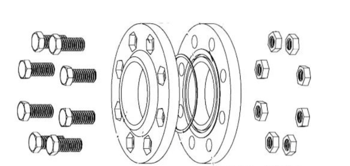
I. Flange Connection Structure
A flange is usually disc-shaped, with bolt holes around the periphery and a hole in the middle through which the pipeline or equipment passes. During installation, two flanges are placed opposite each other, a gasket is placed in the middle, and then bolts are passed through the bolt holes and tightened, thus tightly connecting the pipelines or equipment to ensure that the medium in the pipeline does not leak. At the same time, it can also provide certain support and positioning functions for the pipeline system.
The selection of different materials is based on factors such as the characteristics of the medium in the pipeline, working pressure, and temperature. For example, stainless steel flanges are often selected for chemical pipelines transporting highly corrosive media; while carbon steel flanges can meet the requirements in ordinary water pipeline systems.
II. Types of Flanges
Common pipeline flanges include flat welded flanges, butt welded flanges, socket welded flanges, loose flanges, and threaded flanges.
III. Flange Sealing Surface Forms
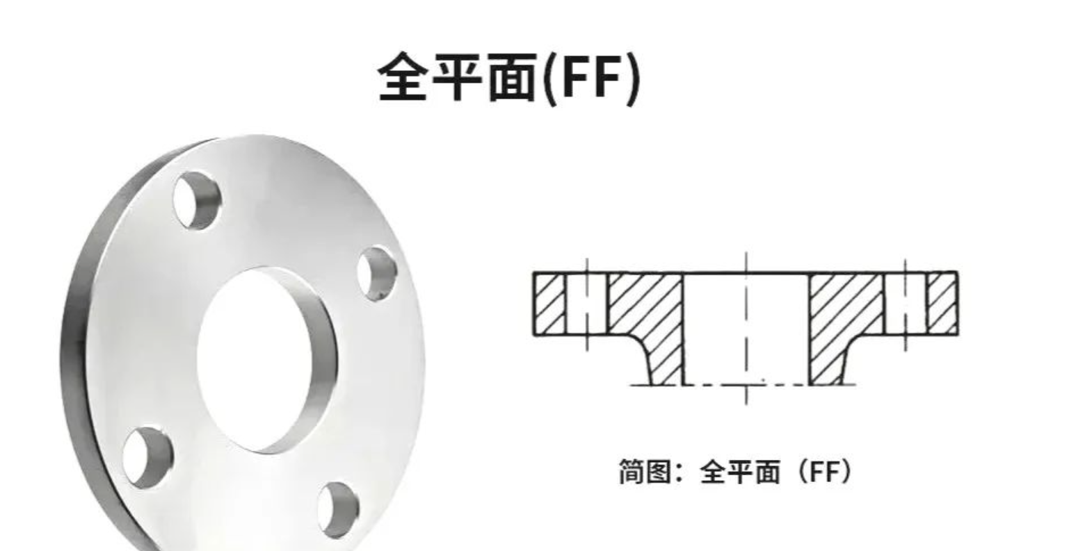
Flange sealing surfaces are divided into flat face, raised face, male and female face, tongue and groove face, and ring joint face.
• Flat Face (FF): The sealing surface is a smooth plane, suitable for occasions with low pressure and non-toxic media, generally used for connections in water pipelines and other less demanding applications.
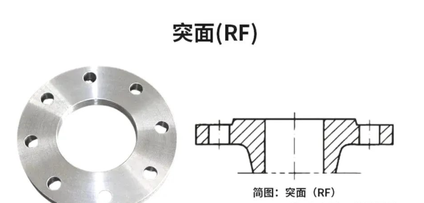
• Raised Face (RF): Also known as a flat sealing flange, the sealing surface is a plane. It has a relatively large contact area with the gasket. After pre-tightening, the gasket is prone to stretching or moving to both sides, resulting in poor sealing performance, and is only suitable for low-pressure occasions.
• Male and Female Face (MFM): Composed of a male face and a female face, they need to be used in pairs during installation. This sealing performance is better than that of flat flanges and is commonly used for pipeline connections of medium-pressure, toxic and harmful media.
• Tongue and Groove Face (TG): The sealing surface consists of a tongue and a groove. The sealing performance is very good and is generally used for the connection of pipelines with flammable, explosive, toxic media and high pressure.
• Ring Joint Face (RJ): A ring-shaped trapezoidal groove is machined on the raised surface of the flange as the sealing surface of the flange. Similar to the tongue and groove face, the flange must be separated axially during installation and disassembly. The possibility of axial separation of the flange must be considered in pipeline design. This type of sealing surface is specially used in conjunction with solid metal gaskets processed into octagonal or elliptical shapes from metal materials to achieve a sealed connection. It has good sealing performance, strict requirements on installation, is suitable for high-temperature and high-pressure working conditions, but requires high precision in gasket processing.
IV. Flange Markings
The following main information is usually provided on the outer ring or near the sealing surface of a flange:
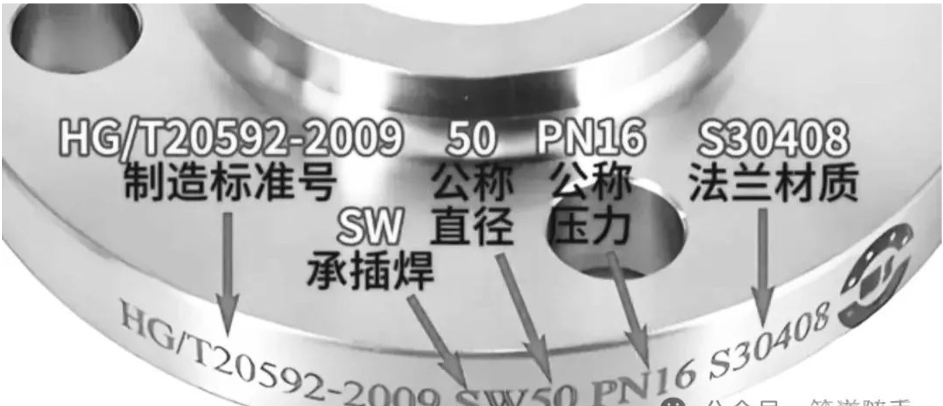
• Nominal Diameter (DN): Indicates the diameter of the pipeline connected by the flange. The unit is usually millimeters (mm). For example, "DN100" means that the flange is suitable for pipelines with a nominal diameter of 100 mm.
• Nominal Pressure (PN): Represents the design pressure that the flange can withstand. The commonly used units are megapascals (MPa) or pounds per square inch (psi). For example, "PN16" means that the nominal pressure of the flange is 16 bar.
American Standard flanges use the CLASS marking. For example, "CLASS 150" indicates that its pressure rating is 150 pounds.
• Material Code: The material of the flange determines its strength, corrosion resistance, and applicable environment. Common material codes include:
◦ Carbon Steel: For example, "A105" represents forged carbon steel.
◦ Stainless Steel: For example, "304" or "316" represent different types of stainless steel.
◦ Alloy Steel: For example, "F22" represents low-alloy steel.
• Standard Code: The design and manufacture of flanges must comply with specific standards, such as:
◦ ANSI/ASME B16.5: American Standard flange.
◦ EN 1092-1: European Standard flange.
◦ GB/T 9119: Chinese National Standard flange.
• Heat Treatment Status: Some flanges are marked with heat treatment processes, such as "N" (Normalized) or "QT" (Quenched and Tempered).
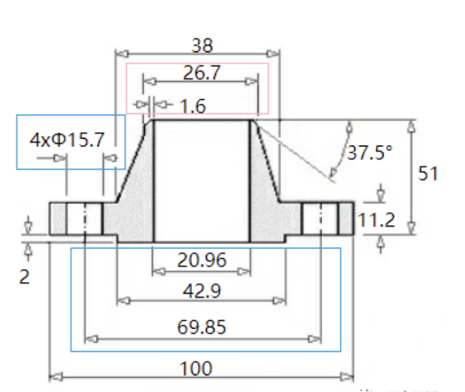
V. Flange Standards and Sizes
The flange standard system is divided into American and European standard systems. The pairing size of flanges (the sealing surface and bolt connection sizes of flanges, as shown in the box in the figure) must be completely consistent to ensure reliable connection and sealing of flanges. Obviously, flanges of different standard series and pressure levels basically cannot be paired. Even if there are exceptions, the scope of exceptions is very small, and generally, this is not done in engineering.
Sometimes, pipelines with inconsistent connection sizes cannot be connected, especially for pipelines where the sizes of metric pipes and imperial pipes differ significantly.